

Signal Converters & Load Cell Signal Converter
Signal Converters
Mantracourt provide a range of signal converter modules which take load cell or strain bridge inputs and provide a data output in a variety of bus and protocol formats. Hardware formats include RS232, RS422 RS485, CAN and USB. Signal converter protocols include Industry Standards such as MODBUS, or Mantracourt’s own proprietary protocols which have been optimised for either ease of use (MantraASCII2) or higher speed communications (MantraBus2).
Desktop & Handheld
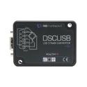
Strain Gauge to USB Converter
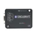
Digital Sensor Card USB – Potentiometer Input
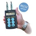
Strain Gauge or Load Cell Handheld Display with RS232 Data Port
Portable Sensor Display Strain Bridge Input
Embedded and PCB Modules
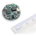
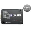
Digital Load Cell Converter
Accessories
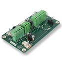
Mount Board for a Single Digital Load Cell Converter
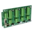
Mount Board for 4 x Digital Load Cell Converters
Desktop & Handheld
DSCUSB Strain Gauge to USB Converter
DSCUSB is ideal for obtaining a simple connection directly into a PC. Powered from the USB port and with simple easy to use DSC Toolkit software available free of charge from our website makes the DSCUSB one of the simplest load cell signal converters available.
Note that the signal converters are also available in an OEM format, contact Mantracourt for details.
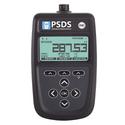
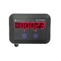
PSD Strain Gauge or Load Cell Indicator
The PSD232 is a handheld signal converter with an RS232 output. Data in an ASCII string format echo’s the current value being displayed. This ASCII string could be used by a serial display such as SERIALDIS, an ASCII datalogger, a PC, a PLC or a Printer. It’s ideal for the laboratory or test applications not requiring a permanent installation.
Embedded and PCB Modules
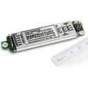
For OEM and system integrators we have a range of load cell signal converters that can be embedded directly into a sensor body such as a load cell using the DCell range or integrated onto a PCB or enclosure using the DSC range. Both these product ranges are available with RS485 or CAN bus connectivity with the DSC also offering RS232. Mantracourt offer a free configuration tool, see Instrument Explorer in our download section website and also found there is the logging software DSCLOG24 for multichannel logging.
Accessories
To support the load cell signal converter modules we have a number of accessories which includes the DS485DIS - a display unit that can sum channels or show individual values from DCell or DSC modules. Field connection boards such as DSJ1 and DSJ4, which make connections for the load cells, communication bus and power simple.
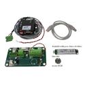
Evaluation Kit
To get started with these products take a look at the Evaluation kits that are available, everything you need to get going at a very competitive price! includes the DS485DIS a display unit that can sum channels or show individual values from DCell or DSC modules. Field connection boards such as DSJ1 and DSJ4 which make connections for the load cells, communication bus and power simple.